How to Identify the 3 Pins of a Transistor correctly: Transistor Testing Methods in Step-by-step

Bipolar junction transistor (BJT) structure
What is a transistor?
Transistors definition: It’s a semiconductor device with three terminals which are collector, emitter and base and transistors are mainly used for amplifying and switch electronic signals.
Who invented the transistor?
Transistors invented by John Bardeen, William Shockley and Walter Brattain. First, they invented Point contact transistor in 1947 and then in 1948, they invented bipolar junction transistor.
Actual construction and the inside view of a Bipolar junction transistor (BJT)
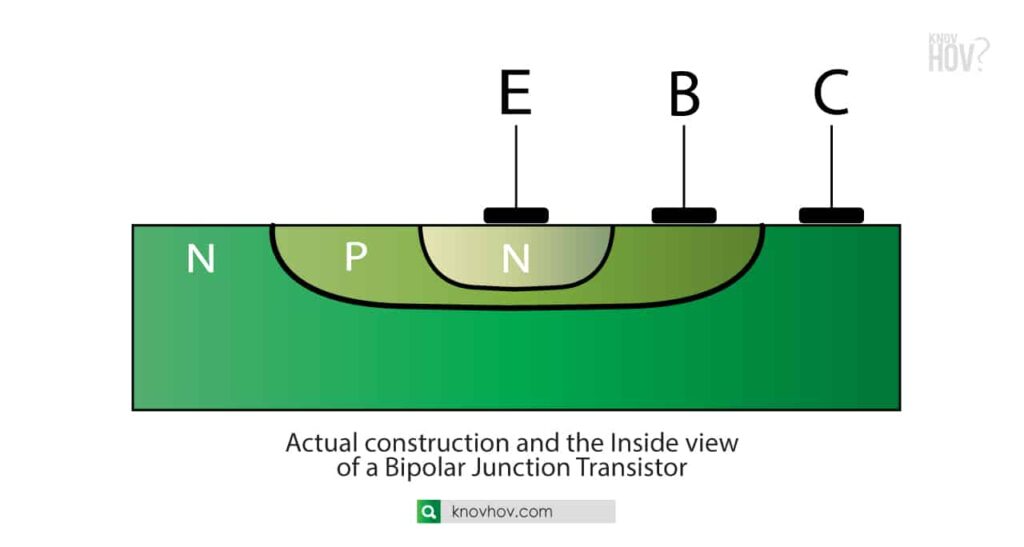
Volume and doping density comparison of bipolar junction transistors (BJT)
The base of a BJT is having the thinnest layer with a small volume and then the Emitter having a medium volume while the collector occupies the largest volume within the bipolar junction transistor.
The doping density of a transistor varies inorder the collector having the lightest doping density and then the base having a medium dope density while the emitter of a BJT transistor having the heavy doping density
Bipolar junction transistors ( BJT )
There are two main types when we consider the transistor types.
- NPN transistors: Two N-type semiconductor layers are separated by one P-type layer.
- PNP transistors: Two P-type semiconductor layers are separated by one N-type layer.
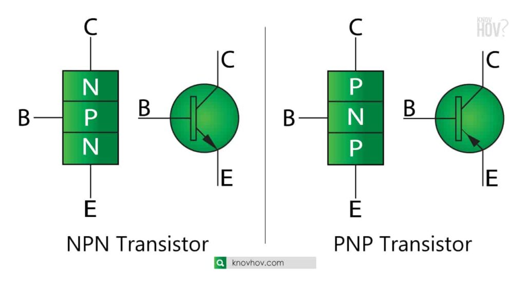
Transistor symbol varies along with the point of the arrow. if the arrow points towards the emitter its an NPN transistor and if the arrow pointing towards the base, its a PNP Transistor.
Transistors NPN vs PNP
In the NPN transistors, the direction of the current is from collector to the emitter while in the PNP transistors the direction of the current is from emitter to collector.
NPN Transistors turns on when electrons enter into the base terminal while the PNP transistors turn on when holes enter into the base terminal.
In NPN transistors the majority charge carriers are electrons and in PNP transistors the majority charge carriers are holes.
NPN transistors are the Most widely using transistor types in the industry.
There are 3 pins of a transistor
- C – collector terminal
- B – base terminal
- E – emitter terminal
Identification of the 3 pins of a transistor is an essential part when using transistors for circuits.
Transistors are made of semiconductor materials mainly silicon and some are made out of germanium and other semiconductor materials.
Transistors are smaller in size and for the operation, it consumes less power when compared to the vacuum tubes which are used in the early stages.
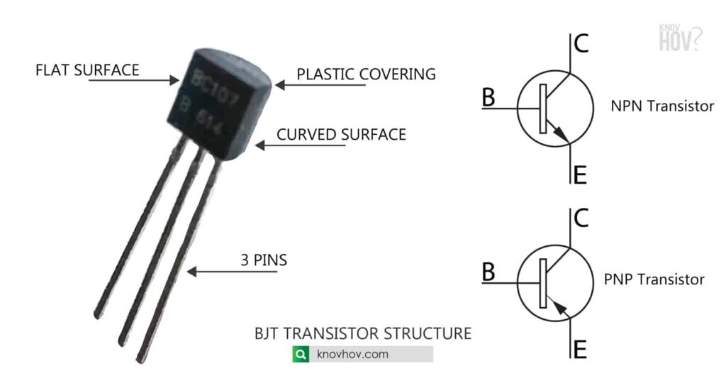
When considering the physical appearance, transistors having a plastic covering and one side of the transistor is a flat surface and other side is curved.
How to identify the 3 pins of a transistor by its symbol
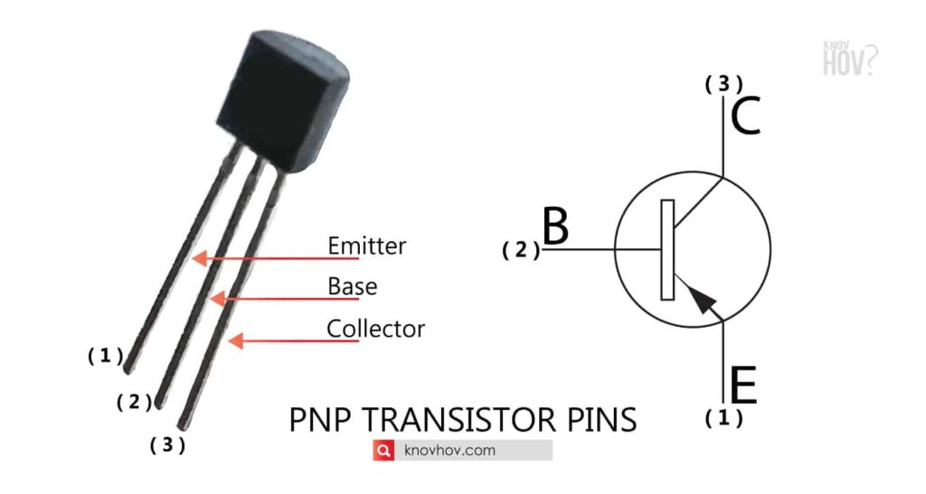
The 3 pins of a transistor symbol can be easily identified by the looking at the direction where the arrow points towards. If the arrow points towards the Emitter, it’s an NPN transistor. If the arrow points towards the base, it’s a PNP transistor.
How to identify the 3 pins of a transistor by its physical appearance
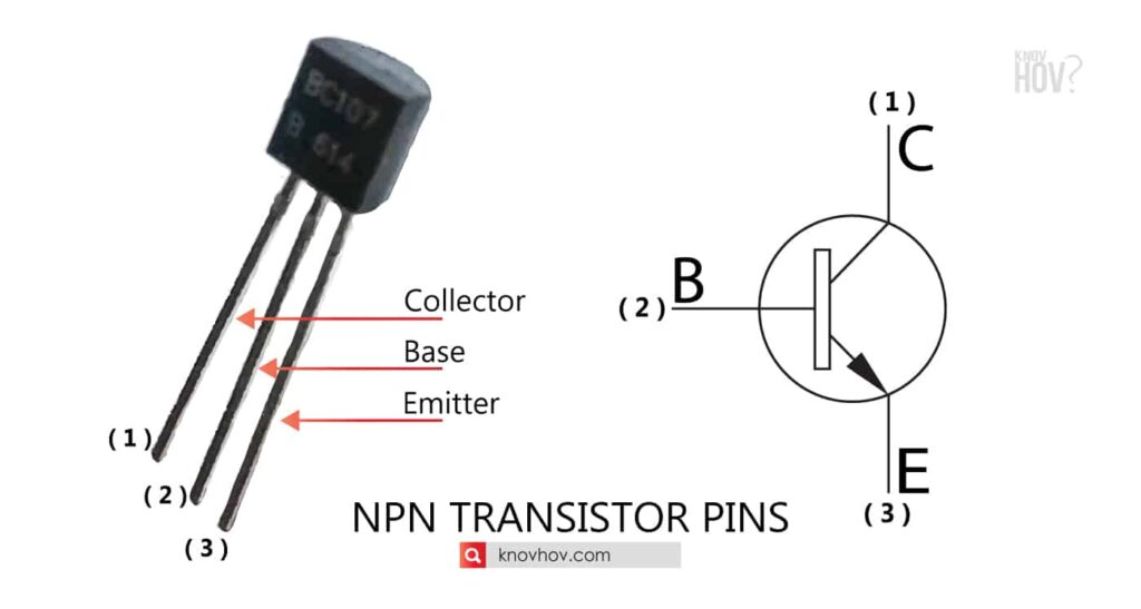
In most cases considering NPN transistors, when we keep the flat side of the transistor front-facing to us. The pins from the left to right are collector, base and emitter respectively. In most of the PNP transistors, it’s getting reversed. So it will be Emitter, base and collector from left to right.
How to identify the 3 pins of a transistor by a multimeter
Identification of the transistor type: NPN transistor or PNP transistor
When analysing the transistor pins, the middle pin of a BJT transistor is always the base and by keeping the positive (Red) probe on the middle pin and negative (black) probe on other two transistor pins, we can identify the transistor type.
- Set the multimeter to the diode mode.
- Then keep the positive (Red) probe of the multimeter to the middle pin of the transistor and then keep the negative (black) probe on one of the other transistor pins on either side.
- If there’s a reading showing in the multimeter screen – it’s an NPN transistor
- If there’s no reading showing in the multimeter screen – it’s a PNP transistor
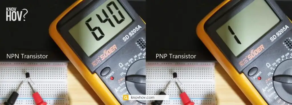
In the diode mode, the multimeter showing a voltage value in a p-n junction where the positive probe is on the anode (p) and the black probe is on the cathode (n)
Identification of the 3 pins of a NPN transistor using Multimeter
- Set the multimeter to the diode mode
- Then keep the positive (Red) probe of the multimeter to the MIDDLE pin of the transistor
- And next, keep the negative (black) probe on the LEFT pin and take the reading from the multimeter.
- Then take the multimeter reading by keeping the black probe on the RIGHT pin of the transistor.
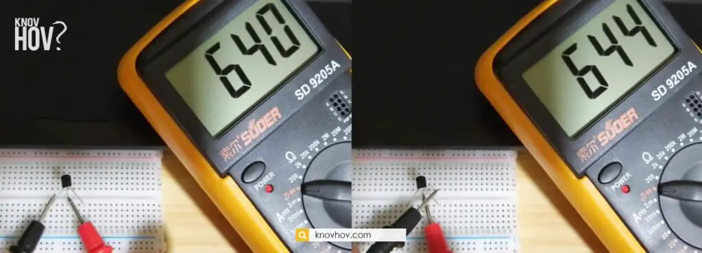
When comparing the two readings, The p-n junction where the higher reading obtained is the base-emitter junction. And the p-n junction where lower value obtained is the collector-base junction.
Same way the above test can be applied to identify the pins of a PNP transistor.
Identification of the 3 pins of a PNP transistor using Multimeter
- Set the multimeter to the diode mode.
- Then keep the positive (Red) probe of the multimeter to the LEFT pin of the transistor
- And next, keep the negative (black) probe on the MIDDLE pin and take the reading from the multimeter.
- Then take the multimeter reading by keeping the positive (Red) probe on the right pin of the transistor.
When comparing the two readings, The p-n junction where the higher reading obtained is the base-emitter junction. And the p-n junction where lower value obtained is the collector-base junction.
Modes of operation of a bipolar junction Transistor
There are 3 main modes of operation in a bipolar junction transistor
- Cut off mode
- Active or linear mode
- Saturation mode
In the Cut off mode, emitter-base junction and the collector-base junction are reverse biased.
In the Active or Linear mode, emitter-base junction forward biased and collector-base junction reverse biased.
In the saturation mode, both emitter-base junction and the collector-base junction are forward biased.
(BJT) Bipolar junction transistors as amplifiers
An amplifier needs 2 terminals to connect the input signal and 2 terminals to connect the load.
So totally there needs 4 terminals but the NPN transistors and PNP transistors having only 3 terminals. Therefore it has to make one terminal common to both input and the output of the transistor.
So there are 3 common rails of a bipolar junction transistor (BJT)
- Common Emitter ( CE )
- Common Base ( CB )
- Common Collector ( CC )
When transistors act as an amplifier, the emitter-base junction keeps as forward biased by applying a DC bias voltage.
The emitter current occurs due to the small voltage input signal contributes to the collector current and the collector current pass through the load resistor which makes a large voltage drop.
A small input voltage turns into a large output voltage using the concept of transistors as amplifiers.
(BJT) bipolar junction transistors as a switch
Transistor switch operation mainly based on the region where the transistor operates in the I-V characteristic curve. The regions where a transistor can operate are active region, saturation region and the cutoff region. If the transistor operates in the saturation region, it acts as a fully ON state while the transistor operates in the cut-off region, it acts as a fully OFF state. Apart from that transistors act as an amplifier if it is operating in the active region.
DO YOU KNOW about Transistor radio ?
The transistor radio is a portable radio receiver which is small in size that mainly using transistor-based circuit within it. Regency TR-1 is the first transistor radio made in 1954 and then Sony TR-63 invaded the market. Then with the time, the use of transistor radio came to an end with boombox and Sony walkman and later with digital devices like mp3 players and mobile phones.
DO YOU KNOW How to find the Anode and Cathode of a Diode? READ IT HERE
